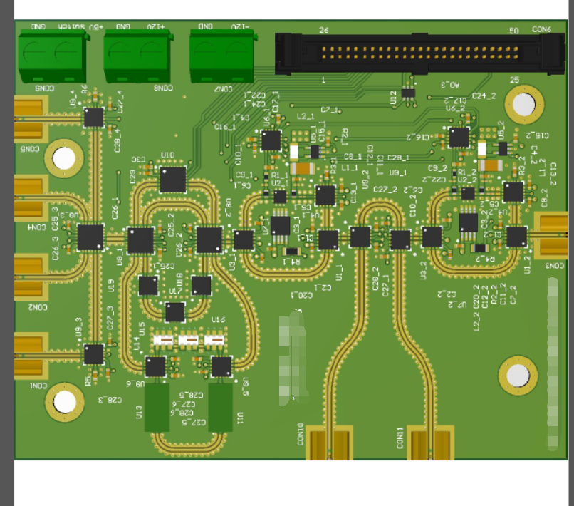
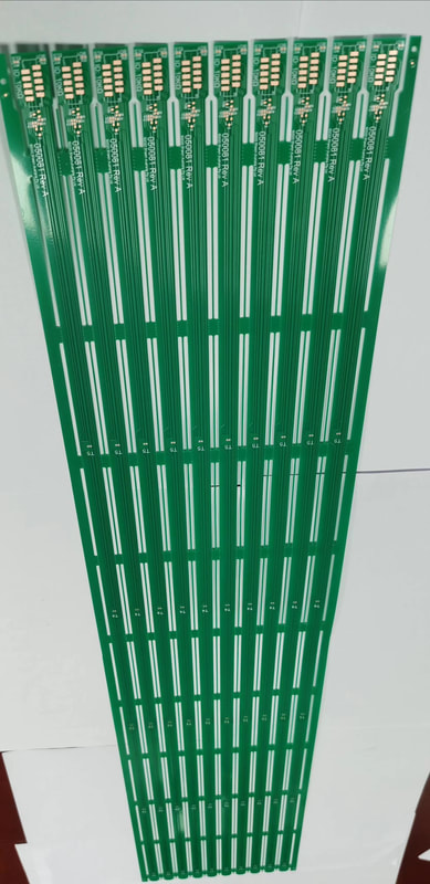
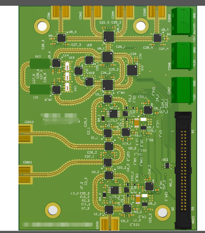
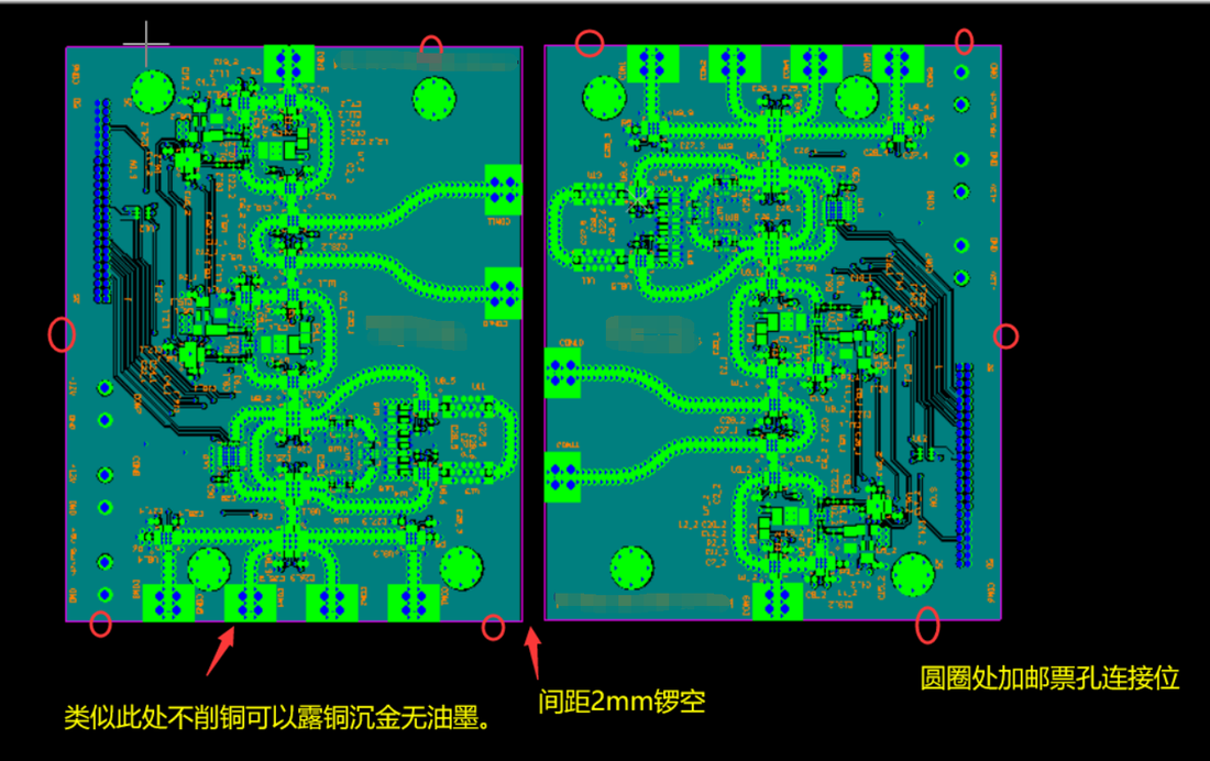
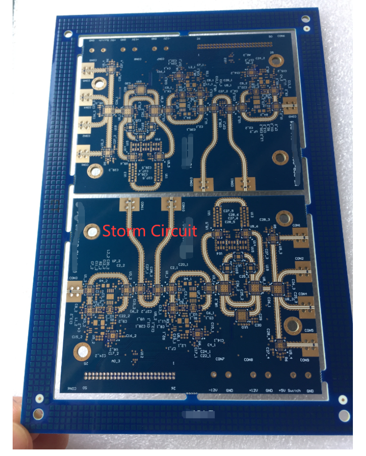
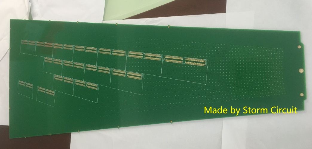
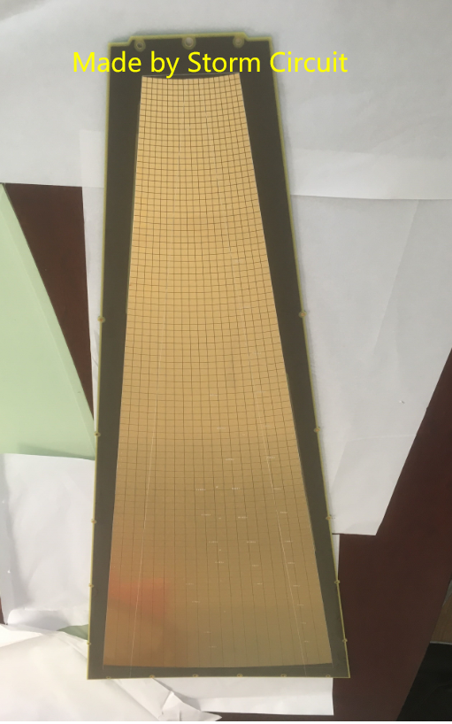
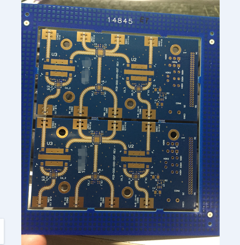
Because of bad experience with weebly.We can not enable SSL for many years,but weebly can not fix this issue.Our latest news change to this link
https://www.stormpcb.com/PCBnews
This is a very long board, the length is over 1200mm.
It is a LED project board, T5 tube. PCB spec:0.8mm, double sided PCB,1200*15mm/pcs, 1200*180/panel. Immersion Gold. Storm Circuit can make very large PCB,we made 8 layer with over 1000mm and 12 layer with over 500mm. they are blind vias. you can find our large board here: http://www.stormcircuit.com/large-pcb.html
0 Comments
PCB specification: Rogers material RO4350B+FR4 (TG170),thickness 1.6mm, blind vias.
RF application. Blind L1-L2, min hole 0.15mm, min trace/space 3/3mil . Exposed copper and gold at the RF connector. Quick Turn: 6 days. Stackup:L1/L2 RO4350B 6.6mil+TG170 FR4 PCB spefication:FR4,2layer,RoHS,
Storm Circuit provides PCB fabrication ,all original components sourcing, function testing and case assembly. All of the components are purchased from manufacturer or Authorized distributors,including the battery holders,Spring antenna,Bluetooth module and all of the ICs. ORIGINAL PHOENIX CONTACT MADE IN GERMANY
Our new components purchased from Phoenix contact arrived. We guarantee our components are original and new , A small 4 layer rigid-flex PCB made by Storm Circuit some days ago. Rigid-Flex printed circuit boards are PCB boards using a combination of flexible and rigid board technologies.Many PCB designers do not know how to design the rigid-flex PCB ,or do not know what information you need to provide to PCB suppliers. We have a rigid-flex PCB design guide here,it may help you. PCB designers have to provide us the rigid part thickness and the flex part thickness, if there is a stackup to show each layer /PP thickness, that helps us much . We made a lot of double sided rigid-flex PCB ,rigid part is usually 1.6mm, and flex part is 0.15-0.2mm.
Here is a 4 layer rigid-flex PCB. Flex part is in inner layers,thickness 0.12mm. rigid part 1.0mm. Usually, 0.4mm pitch BGA circuit board is a bit difficult to do ,but we can make 0.4mm CSP, even,0.38mm CSP PCB ,we can make now. 0.4mm pitch BGA, means the space from BGA ball to another BGA ball is 0.4mm. This PCB is very small,10*10mm, and blind vias from L1-L2,it is 4 layer PCB ,0.6mm, half-hole plating.min hole 0.15mm,via in pad, 0.38mm pitch BGA. All the above features, we can see from below image. Actually,we tried to made with board with standard blind PCB technology,but it is too difficult due to all difficult features put together.At last,we have to make this PCB with HDI technology and drill the blind vias with laser.that is very perfect. We can make such HDI boards in 8-10 days.
Hello everyone,what is the biggest PCB you have seen?400*500mm?500*600mm?No.we made an 8 layer PCB which is much more than above size. that is really the biggest 8 layer PCB we made. We know ,FPC can be very long ,but it is not too wide.FPC (flexible PCB) is made with polyimide material ,the material usually packed in a roll,so FPC usually can be very long . How about rigid PCB,FR4 material? The current biggest we made is 488*1072mm,this is an eight layer PCB with blind vias from L2-L8,high TG material (All 8 layer PCB ,we will use high TG material to do ).min hole 0.2mm,thickness 3.2mm. We made a lot of such big FR4 boards,let us try your design. We made a lot of such boards this year.below is an example what we did.
HDI board,there are four BGA area and three of four are 0.4mm pitch BGA with 0.1mm laser drilling. Material:FR4,TG170. Layer:4 Thickness:0.8mm Finish:Immersion Gold Key feature:0.1mm drilling vias,blind vias,via in pad,Impedance control.0.4mm pitch BGA This board is RF application ,the minimum trace is 3mil and the space is 3 mil too. But the most unusal is there are two cavities on board,the cavities are plated,it is not through from top to bottom .the depth is 10mil from top and plated .
The cavity is for bonding chips,the best surface finishing is ENEPIG for bonding. Storm Circuit made lots of such RF application boards with high frequency material. We made a lot of Rogers material+FR4 board,we call them mix stackup board. All are 6 layer PCB with special stackup. The stackup is as below. The stackup is making like an 8 layer PCB. L1/L2 Core: RO 4350B 6.6mil PP 1080 L3/L4 Core:FR4 PP 1080 L5/L6 Core:FR4 The PCB is 1.6mm, 1oz, blue solder mask,white silkscreen and immerion gold.Another special is the end lanch connector treatment. Trace at the connector is very small,we can not v-groove this board,otherwise,it will damage the trace and make short . Pls see how to load the end lanch connector correclty.it is very strict,the board will not work if any damage. how to load the end lanch connector.see below.
|
sales@stormcircuit.com All rights reserved,2007-2020 Storm Circuit Technology Ltd
|
|